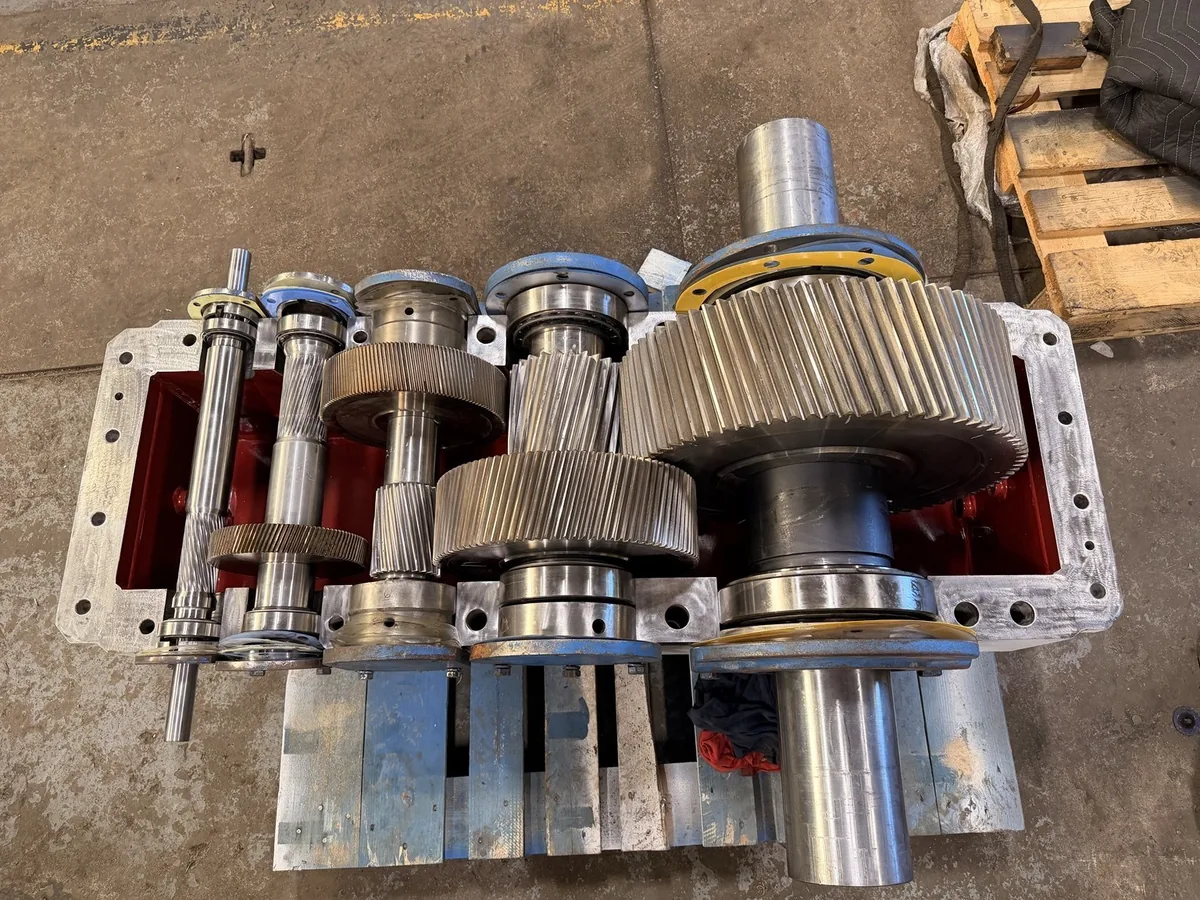
Extruder gearbox repair requires an assessment of torque transmission, screw-drive connections, and the thrust-support arrangement used by the particular machine. A symptom at the gearbox may originate in the drive itself or in changing process resistance. Effective diagnosis connects mechanical findings with screw speed, material conditions, pressure trends, lubrication, and the sequence of the failure.
Single-screw and twin-screw extruders do not share one universal gearbox layout. Their power paths, output arrangements, thrust systems, and assembly requirements differ. Identify the exact manufacturer and model before defining the scope. This page supports repair planning; it does not replace the machine's operating, isolation, or assembly instructions.
What makes an extruder gearbox different?
An extruder drive operates as part of a process that can produce substantial and changing resistance. Its gearbox reduces speed and transmits torque, while the machine's designed thrust arrangement supports axial forces associated with extrusion. Some designs integrate thrust support into the gear unit. Others require assessment of equipment outside the gearbox boundary.
That boundary matters. A bearing called a “thrust bearing” by an operator may not be the component responsible for the measured movement. Obtain an assembly drawing and identify how forces travel from the screw through its connection and supporting structure. The Flender single-screw gear-unit description illustrates one integrated thrust-bearing arrangement; it is not a specification for every extruder.
Single-screw inspection priorities
Relevant areas can include the output shaft, screw connection, thrust-bearing arrangement, reduction gears, housing supports, and oil supply. The evaluation must establish where axial movement is permitted and how it is controlled. Do not assume that every observed movement belongs to a failed gearbox bearing.
Twin-screw inspection priorities
Twin-screw machines may add load-distribution, closely spaced outputs, and synchronization requirements, depending on the design. Record output relationships and component positions during disassembly. Never assume that two similar output components can be exchanged or that a generic timing instruction applies to the machine being repaired.
Common extruder gearbox symptoms
Higher drive load or repeated overloads
A rising motor-load indication can reflect greater process resistance, a screw or barrel issue, drive friction, or another system change. Compare the event with feed rate, material formulation, startup state, screw speed, and pressure records. The gearbox should not be blamed solely because it sits between the motor and the screw.
Preserve the process timeline. A formulation change followed by increased load is useful evidence, but it does not prove the formulation caused internal damage. Likewise, a worn gearbox and a difficult process condition can exist together. The investigation should distinguish correlation from confirmed mechanism.
Heat around the gearbox or thrust area
Excessive temperature may involve lubrication delivery, viscosity suitability, cooling performance, bearing distress, load, or alignment. Record the sensor location and whether the reading is oil temperature, housing surface temperature, or a dedicated bearing measurement. Compare similar production conditions rather than using an unrelated machine's normal value.
Review alarms and protection settings against the applicable instructions. Do not treat thicker oil, a larger fan, or a raised alarm threshold as a diagnosis. Those changes can obscure a symptom while leaving a damaged bearing or restricted lubrication path unresolved.
Axial movement at the output
Unexpected axial movement can involve the thrust arrangement, shaft shoulders, retainers, screw connection, or other supporting parts. Its significance depends on where and how it is measured and the original design allowance. Qualified personnel should perform checks under an approved isolated condition, with stored process and mechanical energy controlled.
Noise, vibration, and unstable operation
Noise can originate in bearings, gears, connections, or the driven process. Record whether it changes with screw speed, material load, or startup. In twin-screw systems, changes in operating behavior require careful review of the complete arrangement; sound alone does not establish a timing error or identify one output shaft as the source.
Oil leakage and contamination
Leaks may involve shaft seals, joints, pressure conditions, or damaged surfaces. Contamination can enter through maintenance, breathing, cooling equipment, or environmental exposure. Identify the oil actually used and any recent additions. A repair should assess the oil system that will be reconnected, not only the cleaned gearbox on the bench.
Diagnosis should combine machine and process records
Prepare the gearbox and extruder identification, screw arrangement, drive rating, normal speed range, and available assembly drawings. Include the symptoms, alarm history, lubricant specification, and previous repair reports. Record production changes before and after the first abnormal observation, including throughput changes and prolonged difficult starts where relevant.
The inspection team needs both the mechanical history and process context. A gearbox may be mechanically damaged even if the process initiated the overload. Conversely, process instability can remain after an otherwise successful drive repair. Assign responsibility for reviewing the screw, barrel, controls, and process equipment alongside the gearbox scope.
Distinguish safe observations from intrusive checks
Existing trends, nameplate photographs, and operator logs can often be collected without disturbing equipment. Coupling removal, shaft movement measurement, internal inspection, and screw-drive separation require the applicable isolation, lifting, and disassembly procedures. Do not open inspection covers or approach moving connections to improve the quality of a fault recording.
Verify what the protection system actually measured
Record the instrument, location, timestamp, and operating state. Motor current, drive-calculated torque, oil pressure, and bearing temperature are different signals. A calculated value may depend on drive configuration. Use the data as evidence with known limitations rather than translating every alarm into a specific internal failure.
The extruder gearbox repair process
Intake and configuration record
Photograph the assembly, connections, external oil equipment, and nameplate. Record the mounting arrangement and any auxiliary devices supplied with the unit. Confirm whether the thrust housing, coupling, motor, or screw connection is included. The receiving team should know which parts remain at the plant and which interfaces still require inspection there.
Teardown of the reduction and output systems
Maintain the identity and orientation of bearings, shims, spacers, shafts, and gears. Document the condition of thrust-related components before separating them. For multi-output arrangements, preserve the relationships needed for correct reassembly and any manufacturer-specific synchronization checks.
Inspection of thrust-support components
Evaluate the bearing elements or pads used by the design, their support surfaces, retainers, lubrication paths, and surrounding structure. Inspect for damage, wear, and signs of inappropriate loading. The correct method depends on the actual bearing type. A rolling-element thrust arrangement and a hydrodynamic arrangement cannot be assessed through an identical checklist.
Inspection of gears and shafts
Check tooth damage, shaft journals, splines or keys, locating shoulders, and relevant runout and fit dimensions. Assess mating components together. Output connections can transfer significant forces; a visibly worn connection may require more than a surface cleanup. The proposed repair should define how original function will be restored and verified.
Lubrication and cooling assessment
Where fitted, examine oil pumps, filters, coolers, lines, flow paths, and monitoring devices within the agreed scope. A blocked passage or contaminated external circuit can compromise a repaired assembly. Record which auxiliary components were assessed and which must be handled by the plant before recommissioning.
Repair approval and assembly
Separate routine replacements from engineering decisions involving restoration, substituted parts, or changed geometry. Reassemble using the applicable fits, bearing settings, gear adjustments, and output relationships. If original requirements cannot be established, keep the uncertainty visible and obtain an appropriate engineering basis before declaring the assembly ready.
How should an extruder gearbox repair be tested?
The test plan should describe what can be demonstrated in the workshop and what remains dependent on the installed extruder. Static checks can establish assembly condition and relevant adjustments. A running test can observe the unit under its stated setup, but an unloaded gearbox run does not reproduce screw torque, process thrust, or the complete machine environment.
If loaded or thrust-related testing is required, establish its availability and acceptance conditions before authorizing the job. Do not infer those capabilities from a generic statement that a gearbox is “fully tested.” The final report should identify speed, load where applied, lubrication conditions, measurements, and limitations.
Coordinate mechanical and process commissioning
At the plant, confirm installation, lubrication-system readiness, alignment where applicable, guards, controls, and protection functions under the approved startup procedure. Return to production in the manner required by the equipment and process instructions. Establish comparable baseline observations for temperature, load, vibration, and oil-system behavior.
The plant should also close the process-side actions identified during diagnosis. If the original event involved a jam, altered formulation, or an unsuitable operating condition, restoring the gearbox alone does not establish that repeating the same duty is acceptable.
Repair versus replacement for extrusion drives
Repair may be attractive when the existing drive remains suitable, critical geometry can be restored, and a replacement would require major changes to the extruder interface. The assessment should consider thrust-system condition, output connections, housing alignment, and availability of acceptable gears and bearings.
Replacement deserves consideration when structural damage is extensive, several critical components require uncertain reconstruction, or production changes exceed the existing design's capability. Compare the complete installed solution, including screw interfaces, mounting, lubrication equipment, controls, and commissioning. A nominally similar torque rating does not establish interchangeability.
Rebuilding and custom components
When damage extends across the assembly, gearbox rebuilding provides the broader restoration framework. If an obsolete gear or shaft is required, custom gear manufacturing must establish its geometry, material, treatment, and mating relationship. Those decisions should remain connected to the extruder's actual duty.
For an unplanned production stop, consult emergency gearbox repair. Emergency coordination can shorten avoidable administrative delays, but the thrust and output requirements still need a defensible technical assessment.
Extrusion applications and operating context
Extrusion machinery is used in plastics, rubber, food processing, and other material-processing applications. Different machines impose different loading, cleaning, temperature, and contamination requirements. Describe the material and process without assuming that an industry label defines the gearbox specification.
A plastics compounding line and a food-processing extruder may both have high-torque drives while requiring different handling and lubricant considerations. Identify the actual equipment, product-contact boundaries, and plant requirements. Examples of applications are not a claim of compatibility with every machine in those industries.
Why consider Industrial Gearbox Service?
Industrial Gearbox Service states that its team brings 50 years of experience in industrial gearbox service and repair. This is a company-provided claim. For an extruder project, the relevant discussion is whether the provider can assess the particular reduction, thrust, and output arrangement and explain the findings in the context of the process.
Confirm model coverage, handling capacity, inspection methods, restoration options, test scope, and technical responsibilities before authorizing work. No manufacturer affiliation, universal twin-screw capability, or guaranteed production outcome is established by this page. The quotation should identify what is included and what the plant or another specialist must complete.
Use the repair brief to gather the machine identification, symptoms, process timeline, drawings, and required return date. The current private preview downloads the brief locally and does not send it. Include the relevant technical contacts so gearbox and process questions can be resolved together.
Build an extruder-specific inspection brief
Organize the brief around three timelines: mechanical symptoms, lubrication behavior, and process changes. Put them on the same sequence of dates or event times. For example, record whether a temperature change began before a material change, after maintenance, or only after a particular startup. This does not prove causation, but it gives the team a better basis for deciding what to inspect first.
Identify the boundaries of the available data. A motor display may show a calculated load, while another sensor directly measures pressure or temperature. Record the instrument and units, and avoid converting values without a documented basis. When comparing trends, note whether speed and throughput were similar. Otherwise, a normal response to a different duty may be mistaken for a developing fault.
Include photographs or drawings that establish the output and thrust arrangement. Label which assemblies will be shipped and which stay on the machine. If the screw connection is damaged, the workshop needs to know whether its mating feature will also be assessed. A technically sound repair to only one half of a worn connection may not restore the required interface.
Finish with a list of open questions for the gearbox, machine, and process teams. Assign each question rather than assuming the repair provider owns every aspect of extrusion performance. That coordination helps the repaired drive return to an understood operating condition.
Frequently asked questions
Why can extrusion process changes affect gearbox condition?
Changes in material resistance, throughput, startup conditions, or speed can alter the drive's duty. Compare the new conditions with the equipment's requirements and investigate actual loads before attributing damage to a single cause.
Does every extruder gearbox contain its own thrust bearing?
No universal arrangement applies. Determine where the machine supports axial forces using its drawings and manufacturer information. The thrust system may extend beyond the gearbox supplied for repair.
What does axial movement at the screw connection indicate?
It may involve the connection, thrust support, retainers, or other components. Interpretation requires an identified measurement location, approved method, and the design allowance. Movement alone does not locate the failed part.
Can a twin-screw gearbox be repaired like a single-screw unit?
Not through an assumed identical procedure. Multi-output designs may introduce synchronization, load-distribution, and arrangement requirements that must be preserved and verified for the particular machine.
Is high motor current proof of a gearbox defect?
No. Process resistance, electrical conditions, mechanical friction, and connected-equipment problems can all affect current. Use the drive data with process records and mechanical findings.
What records help investigate an extruder thrust-bearing problem?
Provide machine drawings, temperature trends, lubrication data, pressure and load history where available, and previous repair records. Identify when abnormal behavior began and whether process conditions changed.
Can contaminated oil damage both reduction gears and thrust support?
It can affect components sharing the relevant oil system. Assess the actual lubrication arrangement and contamination path rather than assuming all parts share one circuit or that damage is confined to one bearing.
Should the screw and barrel be inspected during a gearbox repair?
They may need assessment when process resistance, alignment, or connected damage is suspected. Define that responsibility separately so the gearbox scope does not leave a relevant machine-side cause unexamined.
Does a workshop run reproduce extrusion thrust?
An ordinary unloaded run does not. Any test intended to demonstrate thrust performance requires a suitable setup and agreed conditions. State clearly what the test represents and what remains for site commissioning.
Can we install a higher-power motor after repairing the gearbox?
A motor change can alter available torque and system behavior. The gearbox, screw system, controls, and protections need engineering review before a higher-power drive is treated as compatible.
Why should output splines be checked carefully?
They transmit load and locate connected components according to the design. Wear, damage, or an unsuitable fit can compromise the connection even when the internal gears remain serviceable.
What if overheating occurs only with one formulation?
Preserve comparable speed, feed, load, pressure, and temperature records. The pattern may help identify process-related duty changes, but inspection is still needed to assess whether internal damage has occurred.
Can an extruder gearbox leak because of an oil-system problem?
Yes. Oil level, breathing, circulation, and pressure conditions can contribute alongside seal or shaft damage. Trace the cause before assuming that a new seal alone will solve the leak.
Should both output assemblies be inspected after one side is damaged?
For a coupled multi-output design, assess the interacting components and contamination path. The required scope depends on the design and findings; damage on one side does not prove the other side is unaffected.
Can damaged extruder gears be reverse engineered?
Potentially, when sufficient geometry, material, duty, and assembly information can be established. Severely damaged samples may require additional records or mating components before a reliable manufacturing definition is possible.
What belongs in an extruder gearbox quotation?
Identify the reduction and thrust scope, supplied accessories, inspections, component decisions, assembly requirements, testing, exclusions, and schedule dependencies. Separate process-machine work that remains outside the gearbox repair.
Does replacing the thrust bearing correct excessive process thrust?
No. It restores a component only if the surrounding arrangement is also acceptable. The process and machine loading must be reviewed if they exceed or conflict with the equipment's requirements.
What information is needed for a replacement extruder drive?
Provide ratio, speed, torque requirements, thrust arrangement, output geometry, mounting, lubrication configuration, and machine interfaces. A catalog power figure alone is not enough to establish compatibility.
Why preserve component positions during twin-screw teardown?
The design may depend on specific relationships, adjustments, or synchronization. A traceable teardown record helps prevent apparently similar components from being reassembled in an inappropriate position.
What should be checked before restarting the extrusion line?
Complete the approved mechanical, lubrication, control, guarding, and process startup checks. Verify that causes identified outside the gearbox have been addressed and record baseline observations under known operating conditions.